
7 Step Up Transformer Buying Tips for Global Buyers

A Step Up Transformer can raise voltage efficiently, but the wrong specification can create costly delays, excess losses, or installation problems. Global buyers must look beyond the purchase price. Site conditions, grid frequency, load profile, cooling method, and delivery requirements all matter. Small details matter.

Transformer engineering author James H. Harlow’s work offers a useful buying perspective: “A transformer must be selected for the system it serves, not by nameplate rating alone.” Treat this as a practical paraphrase, not a verified direct quotation. It captures an essential point: a unit designed for one duty may not suit another. A factory’s 50 Hz supply, for example, cannot be assumed to match a 60 Hz project. Nor can an indoor enclosure be presumed suitable for a dusty outdoor site.

This guide presents seven checks to help buyers make clearer comparisons. It covers capacity and voltage ratios, insulation and cooling, efficiency, standards, supplier documentation, testing, and after-sales support. Ask for drawings, test reports, and a clear scope of supply. Check that accessories and spare parts are identified. Then review the assumptions behind the quotation. One thing is easy to miss: lead time may depend on custom design details, not just manufacturing capacity. A careful review helps, though it cannot remove every project risk. Recheck the final specifications with a qualified electrical engineer before ordering.
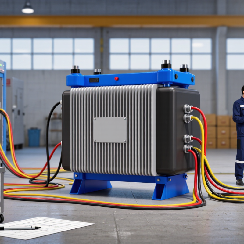
7 Step Up Transformer Buying Tips for Global Buyers

Grid Compatibility: Match Primary/Secondary Voltage and 50/60 Hz Frequency

A step-up transformer must match the site’s actual supply, not just the voltage on a planning sheet. Confirm the incoming primary voltage and required secondary voltage against equipment nameplates. For example, a 400 V supply needing 480 V output requires a transformer rated for that input-output pair. Check whether the site uses single-phase or three-phase power, too. A mismatch can leave equipment underpowered or expose it to damaging overvoltage. Small detail. Big consequences.

Tips: Ask the supplier to confirm the primary and secondary ratings in writing. Compare the nameplate with measured site voltage and expected load. Check tap settings and terminal diagrams before installation; assumptions made during ordering can be costly to correct.

Frequency needs equal attention. Transformers do not convert 50 Hz power to 60 Hz, or the reverse. A unit designed only for 60 Hz may overheat on a 50 Hz supply at the same voltage. Look for a clear 50/60 Hz rating, then verify connected motors and other equipment accept the site frequency. This check is easy to overlook, and voltage compatibility alone is not enough.

Capacity Selection: Calculate Three-Phase kVA with S = √3 × V × I

For a balanced three-phase load, estimate apparent power with S = √3 × V × I. Use line-to-line voltage and line current from the same transformer side. Keep units consistent: volts multiplied by amperes gives volt-amperes. Divide by 1,000 for kVA. A small unit mistake can change the selection.

For example, a 400 V system drawing 100 A requires about 69.3 kVA. That figure describes the calculated load, not automatically the best transformer size. Check the equipment nameplates and measure current under normal operating conditions. Motors, pumps, and compressors may draw higher current during startup. The timing and frequency of these peaks matter.

Allow for realistic operating conditions. Continuous loading, hot enclosures, limited ventilation, and future equipment can affect the required capacity. Avoid adding a large margin without a reason; excess capacity can raise purchase and operating costs. Also, power factor does not belong in the kVA formula. It helps estimate real power in kilowatts, but it does not replace the three-phase capacity calculation. I would verify the assumptions with an electrician or transformer engineer, especially when loads vary through the day. The calculation is useful, but field readings are not always tidy.

Standards Check: Specify Design and Routine Tests under IEC 60076-1

7 Step Up Transformer Buying Tips for Global Buyers

Standards Check: Specify Design and Routine Tests under IEC 60076-1

A step-up transformer is only as dependable as its specification. IEC 60076-1:2011 sets general requirements for power transformers, including ratings, service conditions, connections, and testing. Check the applicable edition and any national deviations before issuing a purchase order. Small details matter.

State the rated power, primary and secondary voltages, frequency, vector group, impedance, tap range, cooling method, and site conditions. These details help prevent mismatched equipment at installation. Request a signed routine-test report, with results tied to the unit’s serial number. Specify applicable tests under IEC 60076-1 and related parts, such as winding resistance, voltage ratio, impedance and load loss, and no-load loss and current. Agree on test records and witness arrangements in writing. Paperwork matters too.

The IEA’s 2023 report, Electricity Grids and Secure Energy Transitions, says annual grid investment needs to nearly double to more than USD 600 billion by 2030. For buyers, clear test records help compare units and support later maintenance decisions. Ask for test-equipment calibration traceability and recorded ambient conditions. A missed tap-range requirement can cause costly rework; this point is easy to overlook, even with a detailed specification.

Efficiency Review: Compare No-Load and Load Losses in Watts at Rated Conditions

For a step-up transformer, compare no-load and load losses as separate watt values. No-load loss occurs whenever the unit is energized, even when little power is being delivered. It mainly reflects energy used in the core. Load loss rises with current and includes winding resistance and stray losses. Ask suppliers to state both figures at rated conditions, not just provide one efficiency percentage.

Check that the readings use the same rated voltage, frequency, tap position, and reference temperature. Load-loss values may need temperature correction, so confirm how the test report handles it. Small details matter. A lower watt figure is useful only when the transformer ratings and test conditions match. A neat spreadsheet can still hide an unfair comparison.

Estimate annual energy cost using your expected operating hours and load profile. A unit running continuously at light load may make no-load loss especially important; a heavily loaded unit may make load loss more significant. Include the local electricity tariff in your calculation. I would not rely on a single quoted number without checking its test basis. Measurement tolerances and real operating patterns can make the final comparison less tidy than expected.

Protection and Reliability: Verify Short-Circuit Withstand under IEC 60076-5

A step-up transformer may face severe electromechanical forces when a fault occurs. IEC 60076-5 sets requirements for verifying a transformer’s ability to withstand short circuits, including thermal and dynamic effects. Request the calculation report or relevant test evidence, not just a generic compliance statement. Match the documented fault level and duration to your actual network conditions.

CIGRE’s 2015 Transformer Reliability Survey, Technical Brochure 642, examined 964 reported failures across approximately 21,000 transformer-years of service. The survey covers varied failure causes; it does not mean short circuits caused every failure. Still, it shows why buyers should examine operating history alongside design claims. A withstand calculation is only useful when its assumptions reflect the installation.

Check the specified short-circuit current, clearing time, impedance, and system X/R ratio. Confirm the winding configuration and tap position used in the assessment. Ask whether the report addresses mechanical forces on windings and supports, not merely conductor heating. Compare the assumed protection settings with the protection scheme planned for the site. A missing assumption matters. An overlooked mismatch can leave a compliant-looking file that does not represent the real duty. Some procurement reviews still accept summary letters too readily; that deserves a second look.

7 Step Up Transformer Buying Tips for Global Buyers - Protection and Reliability: Verify Short-Circuit Withstand under IEC 60076-5

Use this checklist to review a step-up transformer’s ability to withstand external short circuits. The calculation figures below are illustrative estimates, not equipment ratings or test results.

Step Buying check Illustrative data or calculation Evidence to request Acceptance focus
1 Confirm the applicable standard and transformer details. Specify IEC 60076-5, transformer rating, voltage ratio, winding connection, frequency, and required short-circuit duration. A project-specific datasheet and a written statement identifying the standard edition and agreed requirements. The purchase specification and manufacturer’s assessment use the same configuration and stated fault conditions.
2 Check the prospective fault current at the transformer terminals. Example only: for a 1 MVA, 11/0.415 kV transformer with 6% impedance, the idealized LV terminal fault estimate is about 23.2 kA symmetrical RMS, assuming a stiff upstream source and neglecting other impedances. The short-circuit calculation, including system source impedance, cable or bus impedance, and the impedance tolerance used. The calculated fault level reflects the actual installation; the simplified example is not used as a final design value.
3 Verify the short-circuit current and duration used for assessment. Thermal stress depends on current and duration; for a given current, the heating effect is related to the current-squared time integral (I²t). The specified fault current, duration, fault type, and calculation assumptions for each relevant winding. The assessment covers the project’s protection-clearing time and any agreed backup-protection duration.
4 Review both thermal and mechanical withstand. Thermal checks address conductor heating; dynamic checks address electromagnetic forces on windings and supporting structures. Peak current depends on system conditions, including the X/R ratio. The manufacturer’s IEC 60076-5 assessment identifying the methods and assumptions used for thermal and dynamic withstand. Both effects are addressed; a thermal calculation alone is not presented as proof of mechanical withstand.
5 Check impedance and its tolerance against the system study. In the simplified example, 6% impedance gives an estimated fault level of about 1/0.06, or 16.7 times rated current, before accounting for upstream impedance and other system effects. Guaranteed impedance, permitted tolerance, and the fault-current calculation using the applicable impedance value. The design remains suitable at the relevant impedance condition, including the case that produces the higher fault duty.
6 Confirm that short-circuit evidence matches the offered design. Evidence may include an applicable short-circuit test report, design calculations, or other verification accepted for the project and standard requirements. Traceable documentation showing the tested or assessed rating, voltage ratio, winding arrangement, impedance, and relevant design features. Evidence is technically relevant to the offered transformer; differences from the referenced design are explained and assessed.
7 Align protection settings and installation conditions. Compare the transformer withstand assumptions with relay clearing times, breaker operating times, system fault levels, and the intended grounding arrangement. Protection coordination study, relay and breaker data, and written confirmation of any operating limits relevant to short-circuit duty. Protection clears faults within the agreed design basis, and site conditions do not exceed the assessed withstand capability.

Note: The numerical example is a simplified three-phase estimate. Actual fault current and short-circuit duty depend on the complete power-system impedance, transformer impedance and tolerance, fault location, and operating conditions. Confirm the final assessment against the applicable IEC 60076-5 requirements and project specifications.