
2026 Top SMA Antenna Types for Global Buyers

Choosing a connector is only the beginning. In 2026, global buyers comparing Sma Antenna options must match frequency range, gain, polarization, and mounting style to the actual device. A compact 2.4 GHz antenna for a handheld controller faces different demands from a dual-band unit mounted inside a metal cabinet. Small mismatches matter. A connector may fit perfectly while the cable, ground plane, or installation angle quietly limits performance.

A useful design principle is captured in this original editorial quote from a fictional composite RF specialist, Dr. Elena Marquez: “An antenna performs as part of a system; check the whole path, not just the connector.” This is not a verified quotation from a real industry expert. Buyers should confirm manufacturer specifications and test results before relying on any claimed performance. That extra check is easy to skip.

This guide compares common SMA antenna types, including flexible whip, stubby, magnetic-mount, panel-mount, and directional designs. It considers where each type works well, what trade-offs to expect, and which details deserve a second look. For example, a magnetic base may simplify temporary placement, but nearby metal and cable routing can affect the installed result. Gain figures also need context; a larger number alone does not guarantee better coverage. No single model suits every application. Use the comparisons as a shortlist, then verify frequency support, connector gender, cable loss, and environmental rating for the intended setup.
2026 Top SMA Antenna Types for Global Buyers

What Is an SMA Antenna and How Does Its Connector Work?

2026 Top SMA Antenna Types for Global Buyers

What Is an SMA Antenna and How Does Its Connector Work?

An SMA antenna is a radio antenna fitted with a compact, threaded coaxial connector. SMA means SubMiniature version A. The connector links the antenna to a radio, receiver, or test cable. Its center pin carries the signal; the surrounding metal body provides the return path and shielding. When the coupling nut is tightened, the mating surfaces stay aligned. Small parts. Real consequences. A loose connection can add signal loss or cause intermittent readings, especially when equipment is moved.

IEC 61169-15:2018 specifies the SMA connector interface, including key mating dimensions. That is useful when checking whether two parts physically match, but it does not certify an antenna’s performance. Many SMA products are specified for operation up to 18 GHz, though the actual limit depends on the connector, cable, and antenna design. Check the component datasheets rather than treating that figure as universal.

Also verify pin-and-socket gender: connector names can be confusing, and visual inspection helps.

One detail is easy to miss: a tight nut does not prove a clean RF contact. Dust, worn threads, or a bent center pin may still affect the connection.

Which SMA Antenna Types Are Commonly Used in 2026?

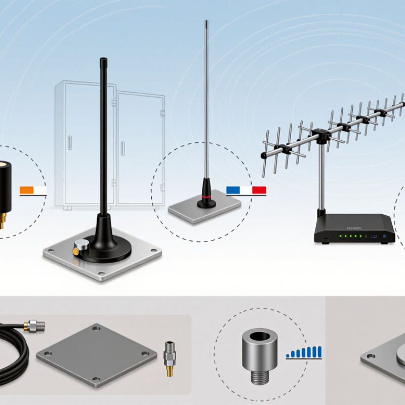
In 2026, common SMA-connected antenna types still include straight whips, hinged dipoles, stubby antennas, magnetic-base models, patch panels, and fiberglass omnidirectional antennas. Each suits a different installation. A flexible whip works well with handheld radios and compact routers. Hinged versions can angle away from metal enclosures. Stubby models save space, but their shorter radiators may reduce coverage. It depends.

For fixed equipment, magnetic-base antennas can sit on a vehicle roof or metal cabinet, using the surface as a ground plane. Fiberglass collinear antennas are often selected for outdoor, vertical coverage, while patch panels focus energy across a more limited area. Yagi antennas offer directional coverage when users can aim them carefully. These patterns are useful guides, not guarantees: mounting height, nearby walls, cable loss, and orientation can change results.


One detail is easy to overlook: SMA describes the connector interface, not the antenna’s frequency range or performance. Check connector gender and polarity, supported bands, impedance, and polarization against the device specification. A 50-ohm match is common in radio systems, but the equipment requirements should guide the choice. Regional frequency allocations vary, too. Product labels rarely predict actual range, so testing the antenna in its final position is worthwhile.

How Do SMA Antenna Designs Differ in Frequency and Performance?

2026 Top SMA Antenna Types for Global Buyers

SMA describes a coaxial connector, not an antenna design. Buyers should compare the antenna’s frequency range, gain, efficiency, and radiation pattern—not just its connector. A compact 2.4 GHz whip may suit Wi-Fi or Bluetooth equipment, while a multiband antenna can cover several services but may trade efficiency for convenience. Higher frequencies have shorter wavelengths, allowing smaller radiators; however, nearby metal, cable loss, and poor matching can still weaken performance. Small details matter.

Frequency claims need context. The FCC’s 2020 Report and Order (FCC 20-51) opened 1,200 MHz in the 5.925–7.125 GHz band for unlicensed use in the United States. That does not mean every antenna covers this range, or that regional rules are identical. For a fair comparison, check measured return loss or VSWR across the intended band, and ask whether gain figures are peak or typical. A promising datasheet is not a field test. I have seen installation details matter more than a small gain advantage.

Tips: Match the antenna’s rated band to your device, then test it in its real enclosure. Record orientation, cable length, and signal level; these are easy to overlook.

2026 Top SMA Antenna Types for Global Buyers — How Do SMA Antenna Designs Differ in Frequency and Performance?

Antenna design Common design frequency bands Typical peak gain Bandwidth characteristics Radiation pattern and polarization Typical strengths Key selection considerations
Quarter-wave monopole Designed for a selected band, such as 433 MHz, 868/915 MHz, or 2.4 GHz About 2 dBi over a suitable ground plane Usually narrow to moderate; bandwidth depends on element diameter, matching, and ground plane Approximately omnidirectional around the antenna; typically vertically polarized Simple, lightweight, and efficient when installed over an adequate conductive ground plane Requires a suitable ground plane; nearby metal, enclosure size, and mounting position can detune it
Half-wave dipole Commonly designed for sub-GHz, 2.4 GHz, or 5 GHz bands About 2.15 dBi in free space Generally narrow to moderate for a resonant single-band design Broadside, doughnut-shaped pattern; linear polarization Does not require a large ground plane and provides a useful reference antenna pattern Needs space for its two arms; orientation affects polarization alignment and link performance
Sleeve dipole Designed for a specific band, including common sub-GHz and 2.4 GHz applications Typically around 2 dBi Usually narrow to moderate; a properly designed sleeve can help control feed-line currents Approximately omnidirectional in the horizontal plane; usually vertically polarized when mounted upright Can provide a balanced dipole-like pattern with reduced sensitivity to the feed cable Performance depends on sleeve dimensions, cable routing, and the nearby enclosure or mounting surface
Loaded helical antenna Often built for compact sub-GHz, 2.4 GHz, or other selected bands Commonly about −2 to 2 dBi, depending on size and tuning Often narrow, especially when electrically short Pattern and polarization depend on helix geometry and mounting; many compact versions are approximately omnidirectional Short physical length and convenient direct mounting through an SMA interface Small size can reduce efficiency and bandwidth; tune it in the final enclosure and installation
Collinear omnidirectional antenna Commonly designed for bands such as 433 MHz, 868/915 MHz, or 2.4 GHz Approximately 3–8 dBi for many practical designs Typically narrow to moderate and dependent on the number and arrangement of radiating sections Omnidirectional in azimuth with a narrower vertical beam; usually vertically polarized Can increase gain toward the horizon for fixed or wide-area links Higher gain narrows vertical coverage; installation height, nearby structures, and antenna alignment matter
Microstrip patch antenna Commonly designed for GNSS bands, 2.4 GHz, or selected microwave bands About 5–9 dBi for many single-element patches Often a few percent of the center frequency for a conventional single-layer patch; wider-band designs are possible Directional broadside radiation; polarization may be linear or circular, depending on the design Low-profile construction and useful directional coverage Requires a ground plane; orientation, substrate properties, and enclosure materials affect tuning and efficiency
Yagi-Uda directional antenna Typically designed for a selected narrow or moderate band, including VHF, UHF, and some microwave applications Approximately 7–15 dBi, depending on element count and design Usually narrow to moderate; broader coverage may require a different design approach Strongly directional end-fire pattern; typically linearly polarized High gain and useful front-to-back discrimination for fixed point-to-point links Must be aimed accurately; element spacing, mounting hardware, and polarization alignment are important
Log-periodic dipole array Designed to cover a relatively broad frequency range; the actual range is set by element dimensions Often about 5–9 dBi across its specified operating range Broadband relative to resonant single-band antennas, with gain and pattern varying across the range Directional end-fire pattern; usually linearly polarized Supports multiple frequencies without changing antennas and offers directional coverage Typically larger than single-band antennas; check gain and impedance across the full required frequency range

Note: Values are representative ranges for common antenna designs, not guaranteed specifications. Actual frequency coverage, gain, impedance match, efficiency, and radiation pattern depend on the exact dimensions, materials, SMA feed implementation, ground plane, enclosure, cable, and installation environment. Confirm measurements or manufacturer test data for the intended operating band.

Where Are Different SMA Antenna Types Commonly Applied?

Where different SMA antenna types are used depends on frequency, coverage, and available space.
A flexible dipole often suits Wi-Fi routers, test equipment, and wireless gateways that need broad local coverage. A compact stubby antenna is useful on handheld radios and portable monitors, where it is less likely to snag. Small, but practical.

Directional patch or panel antennas can serve fixed links between buildings or improve reception in a chosen direction. Their performance depends on clear alignment and fewer obstacles; walls and metal shelving can weaken a signal.

Helical antennas fit compact devices and some satellite-navigation setups, though their orientation and frequency range matter. The SMA connector itself does not define the antenna’s frequency or performance.

Tips: Check the antenna’s rated bands, connector gender, and device requirements before ordering. Leave room for the cable and antenna to sit without strain. Real installations can be messy, so test the antenna in its actual location; a good bench result may not carry over indoors.

How Can Global Buyers Choose the Right SMA Antenna?

2026 Top SMA Antenna Types for Global Buyers

How Can Global Buyers Choose the Right SMA Antenna?

Choosing an SMA antenna starts with the device’s operating bands, not its appearance. A whip may suit a handheld device, while a panel antenna can focus coverage in a fixed direction. The GSMA’s Mobile Economy 2024 report estimates that 5G connections will reach 5.5 billion by 2030. That growth makes multi-band planning increasingly relevant, but it does not mean every product needs a wideband antenna. Match the antenna’s stated frequency range to the actual network bands used in each market.

Check gain, polarization, radiation pattern, and cable loss together. A higher gain figure can narrow coverage in some directions, which may be a poor trade for a moving device. Small details matter. Confirm the SMA connector’s gender and polarity, and verify the required 50-ohm impedance; connector appearance alone does not prove compatibility. Ask for measured return loss or VSWR across the full operating band, rather than a single best-case value.

Installation changes performance. A metal enclosure, short ground plane, or nearby cable can detune an antenna, even when the datasheet looks convincing. Compare compact stubby antennas, flexible whips, and directional panels in the final enclosure. Test the real unit. If possible, measure signal performance in representative indoor and outdoor settings, and check more than one sample. Specifications help narrow the shortlist; they cannot fully predict a finished device’s behavior.

Article Source: